Building a Design Space Map for a Grid-Tied PFC Converter with SIMBA
A grid-connected converter can meet its DC-link target while still hiding poor passive choices. Boost inductance mainly affects input-current quality, while DC-link capacitance governs stored energy and bus ripple. Using the official SIMBA ACDC_PFC_Totem_Pole example, this article builds a compact design-space map showing how these two parameters influence power factor, estimated current distortion, and output ripple.
The goal is deliberately practical: not to claim formal compliance against a grid standard, and not to present a true LCL study, but to show how quickly SIMBA can expose the direction of the trade-offs from real transient simulations.
1. Why start from a design-space map instead of a nominal waveform?
A single waveform is reassuring but narrow. For a grid-connected stage, the same 600 V DC bus can be obtained with several passive combinations that do not behave the same way:
- a small inductance makes the current more jagged
- a small capacitor increases bus ripple
- a larger filter improves waveform quality but changes stored energy and dynamics
- several combinations can satisfy the average voltage target while giving different current quality
This is exactly the kind of question where SIMBA is useful: run the same real circuit several times, keep the metrics that matter, and turn the result into a design-space view instead of a yes/no validation.
Table 1 summarizes the two extreme cases of this sweep.
| Case | L (uH) | C (uF) | Vout avg (V) | Vout ripple (Vpp) | PF | Estimated current distortion (%) |
|---|---|---|---|---|---|---|
| Weak filter | 200 | 400 | 600.00 | 50.68 | 0.9752 | 18.66 |
| Stronger filter | 700 | 1600 | 599.99 | 12.63 | 0.9979 | 5.37 |
The output-voltage target is met in both cases. The difference is in ripple and current quality, not in the average DC value.
2. SIMBA model and sweep definition
The base model is the official SIMBA example ACDC_PFC_Totem_Pole(). For this article, I kept the control structure shipped with the example and only modified:
Ro = 80 ohm, which gives about 4.5 kW at 600 VL1 = 200, 350, 700 uHC1 = 400, 1600 uF
Other key parameters inherited from the example are:
- grid source amplitude: 339.36 V peak at 60 Hz
- switching frequency observed from the gate waveform: about 100 kHz
- transient end time: 0.3 s
Figure 1 shows the actual SIMBA model used as the basis of the sweep.

What is measured from the last 50 ms of each transient run:
Vout_avg: average ofRo - VoltageVout_pp: peak-to-peak ripple ofRo - VoltagePF: average ofv_grid * i_griddivided byVrms * IrmsEstimated current distortion: waveform-derived metric built from the 60 Hz fundamental extracted on the final window
The estimated current distortion used in this article is defined from the measured RMS current and the RMS value of the extracted 60 Hz fundamental:
D_{est} = \frac{\sqrt{I_{rms}^2 - I_{1,rms}^2}}{I_{1,rms}} \times 100
This is a practical waveform-derived distortion estimate, not a formal THD statement under a compliance-oriented FFT procedure.
Transparency note: despite the original roadmap label Grid-tied LCL filter, this study does not use a true LCL grid-filter example. The current environment provides a robust official totem-pole PFC example, and I used it to build a first grid-connected passive design map from real SIMBA runs. The results below therefore compare input inductance and DC-link capacitance in a grid-connected rectifier stage, not a formal three-element LCL compliance study.
3. First sweep axis: inductance improves current quality
Figure 2 shows the effect of increasing L1 for two capacitor values.
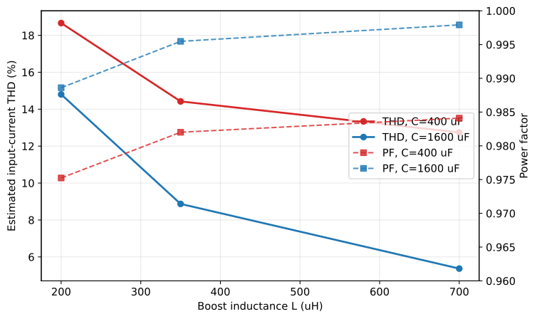
Three points stand out:
- at fixed capacitor value, increasing
L1always improves the estimated current distortion metric - the power factor moves in the same direction and gets very close to unity for the largest inductance
- the benefit is stronger when the capacitor is already large enough to keep the DC bus calmer
At C = 1600 uF, the estimated current distortion drops from 14.80% at L = 200 uH to 5.37% at L = 700 uH, while the power factor rises from 0.9886 to 0.9979.
At C = 400 uF, the same trend exists but starts from a weaker point: estimated current distortion goes from 18.66% to 12.74%, and PF from 0.9752 to 0.9841.
The data also suggest diminishing returns on inductance. Moving from 200 uH to 350 uH brings a strong improvement, while the step from 350 uH to 700 uH still helps but more modestly. Beyond about 350 uH in this sweep, additional inductance should therefore be justified against size, cost, and dynamic impact rather than assumed automatically beneficial.
So the inductance is clearly the dominant lever for input-current shaping in this reduced study.
4. Second sweep axis: capacitor mainly reduces DC ripple
Figure 3 highlights the effect of C1 on the DC bus.
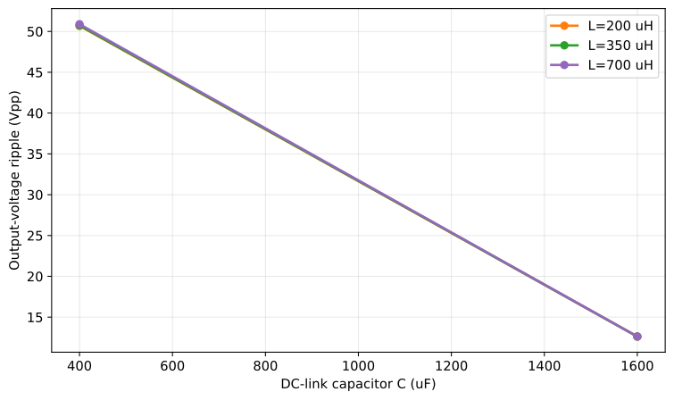
This axis is much easier to interpret:
- for every tested inductance, increasing
C1from 400 uF to 1600 uF reduces the output ripple by about 4:1 - the average output voltage stays essentially unchanged around 600 V
- the capacitor also helps current quality, but less strongly than the inductance
Numerically:
L = 350 uH: ripple drops from 50.73 Vpp to 12.62 VppL = 700 uH: ripple drops from 50.89 Vpp to 12.63 VppL = 200 uH: ripple drops from 50.68 Vpp to 12.63 Vpp
That regularity is useful in practice. Even before a larger sweep, SIMBA makes it obvious that this capacitor range mainly trades stored energy against bus ripple, while the inductance does more of the line-current-cleaning work.
5. The design-space view makes the trade-off visible immediately
This is where SIMBA becomes more compelling than a single case study. Figure 5 turns the six transient runs into a compact map.
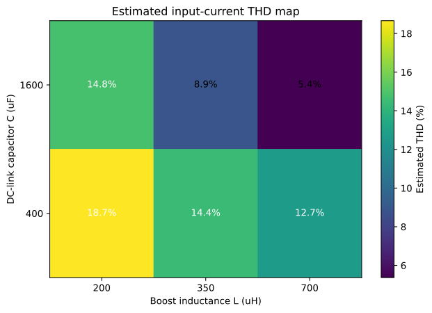
The message is immediate:
- moving right, toward larger
L1, reduces the estimated current distortion in every tested row - moving upward, toward larger
C1, also improves the result, but less strongly - the best region of this sweep is the upper-right corner:
L = 700 uH,C = 1600 uF
This kind of figure is exactly why design-space exploration matters. Instead of asking whether one nominal passive pair works, you can see which region is robust and which region is weak.
6. A Pareto-style view is also useful
Another engineering way to read the same data is to plot one cost against another. Figure 6 compares output ripple and estimated current distortion directly.
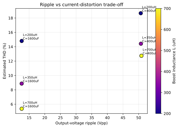
That view is useful because it changes the question from:
- does this case work?
to:
- which passive pair gives the best compromise between bus ripple and current quality?
In this small sweep, the best compromise is again the case 700 uH / 1600 uF, while 200 uH / 400 uF is clearly dominated.
7. What the best case actually looks like
Figure 4 shows the final two grid periods for the strongest passive combination in this sweep: L = 700 uH, C = 1600 uF.
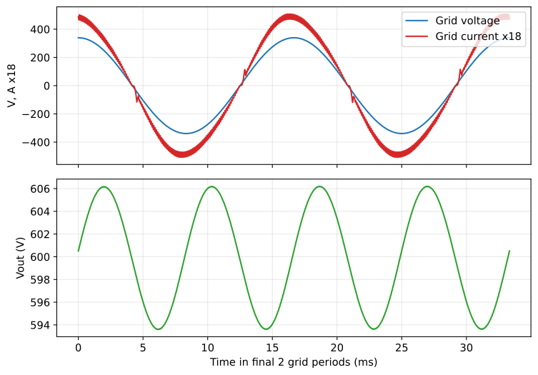
The grid current follows the voltage much more closely than in the lighter-filter cases, and the DC output stays confined to a narrow ripple band around 600 V. For this operating point, the measured indicators are:
Vout_avg = 599.99 VVout_pp = 12.63 VPF = 0.9979Estimated current distortion = 5.37%
This does not prove compliance against a harmonic standard, but it is already enough to identify one of the most balanced regions of this small design space.
8. Practical takeaway
This article suggests a simple engineering reading of the sweep:
- if the DC-bus ripple is the main problem, increase
C1 - if the line current quality is the main problem, increase
L1 - if both are weak, changing only one passive is usually not enough
More broadly, the article shows the workflow value of SIMBA for grid-connected stages:
- start from an official example that already runs
- expose the passive axes that matter
- keep only defensible waveform-derived metrics
- build a compact design-space map before going to a larger sweep or a standard-compliance study
The six real transient runs of this study were enough to make the trade-off visible. That is the practical point: SIMBA lets you move from a nominal case to an engineering map quickly enough to support early filter decisions.
The next logical step would be a strict LCL study with inverter-side inductance, grid-side inductance, and filter capacitor all swept explicitly. That would be the right setup for discussing resonance placement and damping. This article stops one step earlier and focuses on a robust, reproducible operating-map method using an official grid-connected PFC example.
9. Reproducing the study in SIMBA
The complete workflow is a simple nested sweep around the official example:
results = []

for L in [200e-6, 350e-6, 700e-6]:
    for C in [400e-6, 1600e-6]:
        results.append(run_case(R=80.0, L=L, C=C))
Inside run_case, the script:
- loads
simba.DesignExamples.ACDC_PFC_Totem_Pole() - updates
Ro,L1, andC1 - runs one transient simulation
- extracts
Ro - Voltage,AC1 - Voltage, andAC1 - Current - computes average output voltage, ripple, PF, and the estimated current distortion metric on the final 50 ms window
The full numerical results used for all figures are stored in the article assets as grid_tied_pfc_lc_sweep.json.
References
- SIMBA documentation, Python API examples and design examples,
doc.simba.io/ - R. W. Erickson, D. Maksimovic, Fundamentals of Power Electronics, 2nd ed., Springer
- S. Buso, P. Mattavelli, Digital Control in Power Electronics, 2nd ed., Morgan & Claypool
- J. Sun, small-signal methods and impedance-based thinking for grid-connected converters, various IEEE tutorials and papers
About the Author
Sophia is a power electronics engineer at Powersys, focused on SIMBA, converter design workflows, and reproducible simulation methods for real engineering decisions.
Autonome: all numerical values, waveforms, and figures in this draft come from real SIMBA transient simulations executed on 2026-08-28 from the official ACDC_PFC_Totem_Pole example, with only Ro, L1, and C1 modified programmatically.


