Six-Phase PMSM co-simulation with a JMAG FEA Model Using Subcycling
Download JMAG port information xml
Introduction
The JMAG direct coupling block in the SIMBA Model Library runs co-simulation with a JMAG finite element analysis (FEA) model. When using this block, the FEA will be performed while exchanging physical values, such as voltage, current, and torque, with power electronics circuits in SIMBA.
This example demonstrates how to set up and run a six-phase PMSM drive-system co-simulation with a JMAG FEA model using the subcycling feature.
JMAG is an FEA software developed by JSOL Corporation for the design and simulation of electromagnetic components, including motors and transformers. Both JMAG and JMAG-Designer are registered trademarks of JSOL Corporation. (https://www.jmag-international.com/)
Prerequisites
To use the JMAG direct coupling block, you must have JMAG-Designer installed on your computer. For the JMAG operation and licensing information, contact a JMAG distributor in your region listed in this link (https://www.jmag-international.com/aboutus/members/)
Info
JMAG requires an environment variable named "InsDir" to be defined on your machine. This variable must be set to the path of the JMAG installation folder. For instance, if you have installed JMAG v24.1 in the default directory, you should set the variable as follows: InsDir=C:\Program Files\JMAG-Designer24.1
Highlights of SIMBA Features Demonstrated in This Example
Co-simulation
Co-simulation is a framework that combines two or more solvers to simulate a single system. In motor drive transient analysis, this typically involves coupling circuit simulators with electromagnetic Finite Element Analysis (FEA) to capture detailed motor behavior, including field distributions and converter switching effects.
Unlike FEA base lookup table models which uses equivalent circuits and motor parameter tables generated by FEA, co-simulation does not require extensive pre‑computation time. This advantage can be particularly important when simulating multi-phase motors. In general, the higher the number of phases in the motor, the higher the number of dimension for the motor parameter table. It is because all possible combination of current conduction in the phase needs to be covered in the tables. Consequently, co-simulation can be a more practical solution than FEA-based lookup-table models for machines with a large number of phases.
SIMBA provides this electromagnetic FEA co-simulation capability through the JMAG Direct Coupling block.
Subcycling
Subcycling is a technique in co-simulation to advance subsystem simulation using its own smaller internal time steps while synchronizing with other subsystems or higher-level systems at larger intervals.
In SIMBA, subcycling is provided as an option of JMAG Direct Coupling block. Subcycling is enabled when the subcycling rate N is defined as more than 1 in Direct Coupling Block Property Panel. For instance, when N=5, SIMBA calls the JMAG solver every 5 simulation steps. Also, in order to ensure the accuracy around the discontinuous point, SIMBA calls JMAG solver whenever the switch status changes in addition to the interval defined by the subcycling rate N.
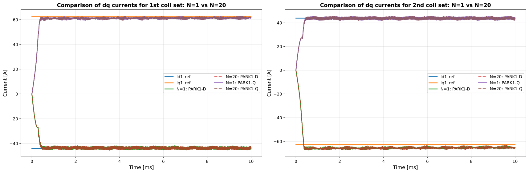
In this example, the results obtained with N = 1 (no subcycling) and N = 20 are compared.
Motor drive inverter model
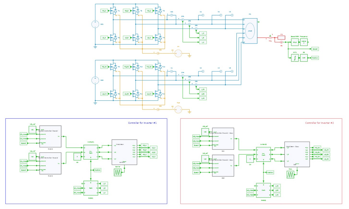
Inverter and control
The motor drive inverter model consists of two of 3-phase 2-level voltage source inverters (VSI) and the current vector control with PI current regulator. The details of control can be found in another example.
Motor
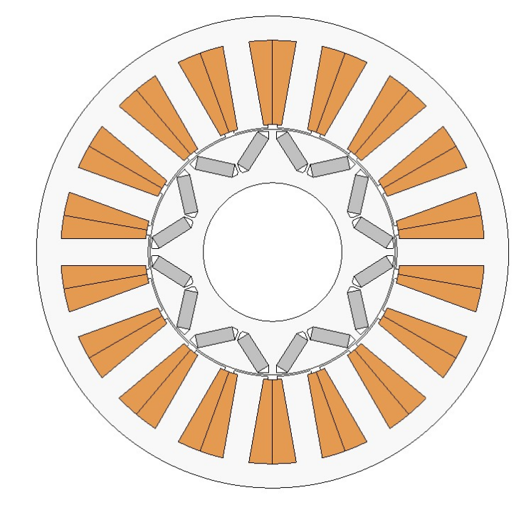
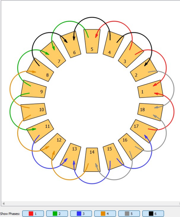
This example uses an 8-pole, 18-slot, six-phase PMSM with the specifications listed in the table below.
| Motor specifications | |
|---|---|
| Motor Type | PMSM |
| Max. Power | 80 kW |
| DC Voltage | 600 V |
| Max. Current | 250 A |
| Number of Poles | 8 |
| Number of Slots | 18 |
| Number of Phases | 6 |
| Magnet | NdFeB, Br=1.0T |
| Core Material | 50A1000 |
In below, the left shows a motor cross section view and the right shows the winding configuration.
Settings
Co-simulation settings in JMAG and SIMBA
For detailed co-simulation setup procedures, refer to previously published article Co-simulation with JMAG FEA Model.
Results
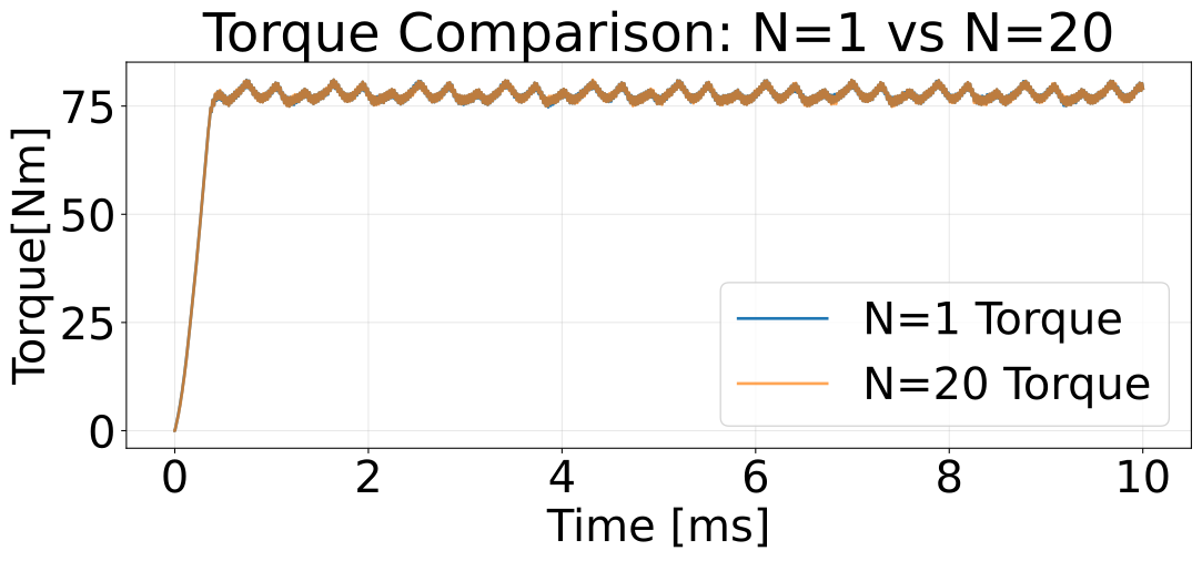
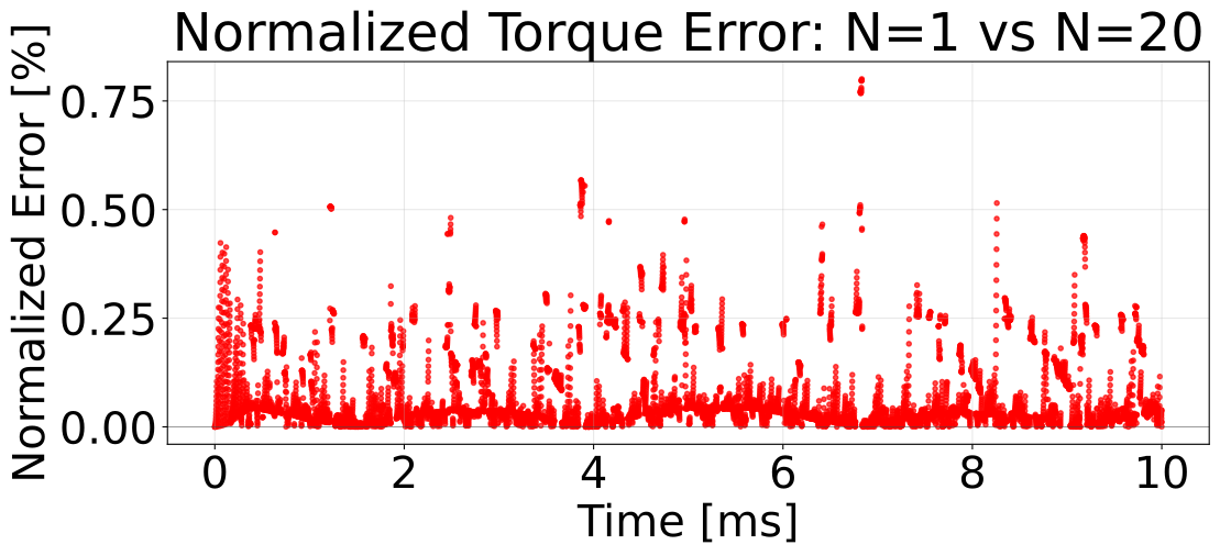
The figures below compare the results obtained with N = 1 and N = 20 for the six-phase PMSM co-simulation.
The normalized relative-error plot shows a maximum error of 1.75% for the current waveform and 0.8% for the torque waveform.
Computation time is reduced from 70 minutes (N = 1) to 23 minutes (N = 20) while maintaining practical accuracy. Intel(R) Core(TM) i9 3Ghz, 64 G byte RAM was used for this comparison.